
Page 80 - Lehrbuch Neigungsmessung deutsch 2018.indd
P. 80
COMPENDIUM INCLINATION MEASUREMENT
WYLER AG, WINTERTHUR / SWITZERLAND
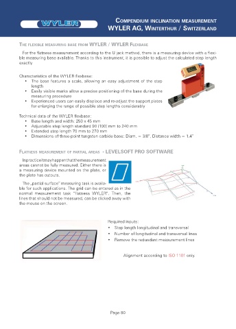
THE FLEXIBLE MEASURING BASE FROM WYLER / WYLER FLEXBASE
For the flatness measurement according to the U jack method, there is a measuring device with a flexi-
ble measuring base available. Thanks to this instrument, it is possible to adjust the calculated step length
exactly.
Characteristics of the WYLER flexbase:
• The base features a scale, allowing an easy adjustment of the step
length
• Easily visible marks allow a precise positioning of the base during the
measuring procedure
• Experienced users can easily displace and re-adjust the support plates
for enlarging the range of possible step lengths considerably
Technical data of the WYLER flexbase:
• Base length and width: 250 x 45 mm
• Adjustable step length standard 90 (100) mm to 240 mm
• Extended step length 70 mm to 270 mm
• Dimensions of three-point tungsten carbide base: Diam. = 3/8”, Distance width = 1.4”
FLATNESS MEASUREMENT OF PARTIAL AREAS - LEVELSOFT PRO SOFTWARE
In practice it may happen that the measurement
areas cannot be fully measured. Either there is
a measuring device mounted on the plate, or
the plate has cutouts.
The „partial surface“ measuring task is availa-
ble for such applications. The grid can be entered as in the
normal measurement task “flatness WYLER“. Then, the
lines that should not be measured, can be clicked away with
the mouse on the screen.
Required inputs:
• Step length longitudinal and transversal
• Number of longitudinal and transversal lines
• Remove the redundant measurement lines
Alignment according to ISO 1101 only.
Page 80