
Page 90 - Lehrbuch Neigungsmessung deutsch 2018.indd
P. 90
COMPENDIUM INCLINATION MEASUREMENT
WYLER AG, WINTERTHUR / SWITZERLAND
The frequency difference of approx. 100,000 Hz assures that, even when a high measuring rate is ap-
plied (numbers of measurements per second), an excellent resolution is available. Most of the existing
measuring instruments have an output rate of ±2 volts. This output rate is equal to a possible range of
±2,000 digits. This is certainly not enough for accurate measurements. The implemented calibration curve,
stored in the sensor’s head allows easy calibrating and leads to excellent results even when using large
angles.
The high stability and accuracy of the ZEROTRONIC sensors is, among other things, based on the fact
that only one single oscillator is applied which is switched by a SELECTOR alternatingly to the two elec-
trodes. This approach ensures that temperature influences can be minimized and the long-term stability is
optimized.
The frequency-differences between the two oscillating circuits are measured digitally and out of these
values the inclination is calculated. Thanks to this concept, the signal-to-noise ratio can be optimized and
the inclination can be detemined very accurately.
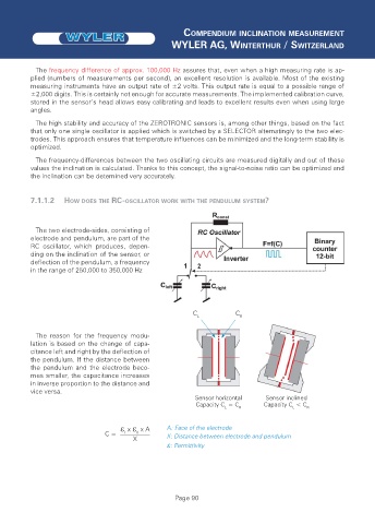
7.1.1.2 HOW DOES THE RC-OSCILLATOR WORK WITH THE PENDULUM SYSTEM?
The two electrode-sides, consisting of
electrode and pendulum, are part of the
RC oscillator, which produces, depen-
ding on the inclination of the sensor, or
deflection of the pendulum, a frequency
in the range of 250,000 to 350,000 Hz
C L C R
The reason for the frequency modu-
lation is based on the change of capa-
citance left and right by the deflection of
the pendulum. If the distance between
the pendulum and the electrode beco-
mes smaller, the capacitance increases
in inverse proportion to the distance and
vice versa.
Sensor horizontal Sensor inclined
Capacity C = C Capacity C < C
L R L R
x x A A: Face of the electrode
C = r 0 X: Distance between electrode and pendulum
X
: Permittivity
Page 90