Machine-building industry
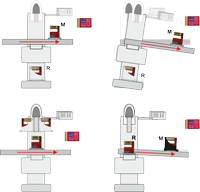
MACHINE TOOLS / CHECKING OF ROTATION ERRORS


Subject:
All machine tool manufacturers highly value rotation measurements since they allow a reliable judgement of the quality of a machine tool with little effort.
Measuring task:
Pitch and roll values on a machine must be determined. The measurement should be done reliably and efficiently.
![]()
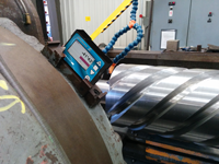
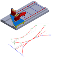
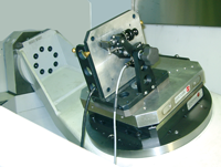
MEASUREMENT OF PITCH AND ROLL ON A GRINDING MACHINE

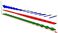
Subject:
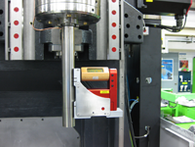
A manufacturer of large metal plates has several large surface grinding machines in his workshop. The geometry of these machines must be checked and documented periodically, and, where required, to be corrected.
Measuring task:
On a large surface grinding machine with guide ways with a length of 18m pitch and roll must be checked. The maximum tolerance is 0.1 mm/m.
![]()
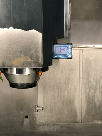
MEASUREMENT OF THE RECTANGULARITY OF THE HEAD OF A ROUND TABLE GRINDING MACHINE
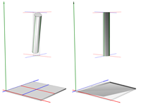
Subject:
A manufacturer of large metal plates has several large surface grinding machines in his workshop. The geometry of these machines must be checked and documented periodically, and, where required, to be corrected.
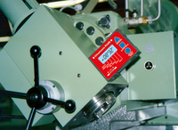
Measuring task:
The rectangularity of the axis of a grinding head of large grinding machine in relation to the bearing of a round table with a diameter of 3200 mm must be measured. Based on the results, if necessary, the inclination of the head must be adjusted.
![]()
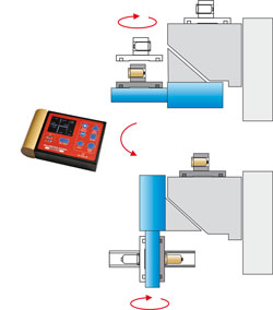
MACHINE TOOLS / CHECKING OF ROTATION ERRORS
Subject:
Machine tools must be checked periodically for geometrical deviations, since changes of the geometry have a direct influence on the quality of the parts manufactured on that machine.
It is very important that during the displacement in one axis the tool will follow a straight path compared to the table. On machines of light-weight construction the table can show a deformation due to its own weight.
If the complete machine construction is tilting during the displacement of the table this is a sign for insufficient stability of the foundation or for a flexibility of the stand (damping elements).
Measuring task:
The geometry of a machine tool must be verified. The check must show rotational errors of the table during displacement. The measurement should be made reliably and efficiently.
![]()
EFFICIENT CHECKING OF THE ALIGNMENT OF A MACHINE / CASE 1 + 2
Subject:
Customers often have the need to verify whether a machine is still in tolerance after e.g. a crash or during the yearly maintenance on the machine.
Calling in an external technician might be too cumbersome, too time consuming or too costly.
Measuring task:
Efficient checking of the machine.
![]()
MACHINE TOOLS / CALIBRATION OF SURFACE PLATES, STRAIGHT EDGES AND SQUARES

Subject:
The quality of granite references like surface plates, straight edges or squares must be checked and certified regularly.
Measuring task:
The measurement and calibration of granite master squares and surface plates should be performed efficiently.
![]()
MACHINE TOOLS / MACHINE TOOLS / POSITIONING OF A CUTTING HEAD
Measuring task:
The position of a cutting head or the table must be checked and adjusted if necessary.
![]()
SCREW PUMP / ADJUSTMENT OF GRINDING ANGLE
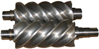
Subject:
The performance and efficiency of a screw pump is strongly depending on the precision of the 2 screws.
Measuring task:
Precise adjustment of the grinding angle during production of the screws. This task is impeded by the fact, that during adjustment the display of the instrument cannot be seen.
![]()
MECHANICAL ENGINEERING / INCLINATION OF A HUGE BEARING RING
Measuring task / Goal:
Checking the inclination at various positions of a huge bearing ring.
![]()
MECHANICAL ENGINEERING / MACHINE TOOLS / ADJUSTMENT ANGLE OF A TOOL
Measuring task / Goal:
Checking the adjustment angle of a tool on a large rotating lathe.
![]()
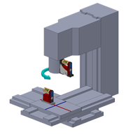
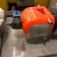
MACHINE TOOLS / SPINDLE ALIGNMENT
Subject:
The main spindle of a milling machine can be set for vertical as well as for horizontal milling. To change between the two settings, the milling head rotates on a bearing set at 45°.
Measuring task:
The deviation from the right angle between the two working positions “horizontal” and “vertical” must not exceed 2 arcsec.
The measurement (and correction) is first made during assembly, and again during final inspection of the finished machine.
![]()
MEASUREMENT OF THE ABSOLUTE POSITION OF A Guideway
Subject:
The straightness of a guide way can be measured very easily and very precisely with the software wylerSPEC. Since the straightness is independent of the absolute position of the guide way in space, it is enough to measure “relative”. On the other hand, when adjusting a machine, it can be very helpful to know the exact position of the guide way in space.
Measuring task:
For a guide way, not only its straightness but also its deviation from the horizontal plane shall be measured. Furthermore, it should be shown where and how much the guideway should be corrected to adjust it horizontally.
![]()
FLATNESS MEASUREMENT ON A CIRCULAR SUPPORT OF A TURN TABLE
Subject:
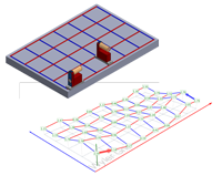
Module 4 of the software wylerSPEC allows users to determine the flatness of a rectangular surface very easily. The measurement of the flatness of a circular support though, as it is used for large machine tools, is much more complex.
Measuring task:
The flatness of a circular support with a diameter of 2.3m must be determined.
![]()
ALIGNMENT OF AN INJECTION MOLDING MACHINE WITH WIRELESS INCLINATION SENSORS

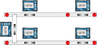
Subject:
Each injection molding machine must be properly aligned during commissioning. This process uses 5 precision spirit levels and requires 2 technicians. One of them is reading the spirit levels and the other one is adjusting the 6 supports. This is an iterative and tedious work, since all 5 spirit levels must be re-checked after every adjustment. The available height on each of the 5 measuring points is limited to 120 mm.
Measuring task:
The customer is searching for a more efficient solution for this process during in-house commissioning as well as for the commissioning
at the customers premises. If possible, the adjustment should be done by one single technician. To assure that no instrument is accidentally pulled down, a wireless solution is favored.
![]()
POSITIONING OF A HEAVY PART WITH AN OVERHEAD CRANE
Subject:
In a large production hall, a heavy part shall be positioned in the correct height with an overhead crane in order to allow a stress-free mounting. First tests show that the building is not stable enough: Depending on the weight of the part, vertical offsets are measured which are larger than the required positioning
accuracy.
Measuring task:
In order to achieve the required accuracy, the bending of thebuilding respectively of the overhead crane should be measured.From these values, the vertical correction of the crane should be calculated.
![]()
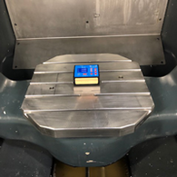
MACHINE TOOLS / ANGULAR POSITIONING ERROR OF A- AND C-AXIS
Subject:
Machine centers capable of machining freely designed shapes, require, next to the linear axes X, Y and Z, the rotary axes A and C as well. In order to manufacture work pieces with adequate precision, the rotary axes A and C must provide the same high angular positioning accuracy as the linear axes.
Measuring task:
To measure deviation from nominal angle at different angular positions. To avoid errors due to the mass of the machine components, the measurement should be collected as close as possible to the cutting position.
The measured values shall be used as corrective factors in the CNC controller. Uncertainty of measurement should not exceed 2 arcsec.
![]()
LARGE GRINDING MACHINE WITH FLAT GUIDEWAYS
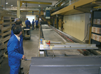
Subject:
A manufacturer of large metal plates has several large surface grinding machines in his workshop. The geometry of these machines must be checked and documented periodically, and, where required, to be corrected.
Measuring task:
On a surface grinding machine with 18-meter-long guideways, set 1.3m apart, the parallelism of the two guideways must be checked periodically. The guideways must be within a plane with a maximum tolerance (error) of less than 0.1 mm. The complete machine and its guideways can be adjusted by means of supporting screws placed at 750 mm intervals.
![]()
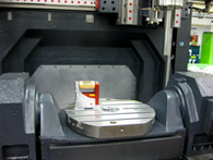
MEASUREMENT OF A CIRCLE ON A ROUND TABLE OF A GRINDING MACHINE
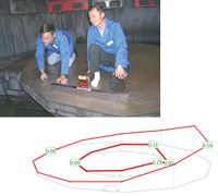
Subject:
A manufacturer of large metal plates has several large surface grinding machines in his workshop. The geometry of these machines must be checked and documented periodically, and, where required, to be corrected.
Measuring task:
The flatness of a rotating table of a grinding machine with a diameter of 3200 mm must be measured. Thereby only the flatness of a circle must be measured and not the whole table.
![]()
ALIGNMENT OF THE HOLES OF FLANGES

Subject:
A pipe must be welded in between two vertical flanges with holes. These pipes have a length between 2m and 10m and a diameter between 400mm and 1000mm.
The material of the flanges and the tubes is either aluminum or stainless steel.
Measuring task:
Before the welding process, the holes of the 2 flanges must be aligned in such a way that the holes on the left have less than ±15arcsec deviation from the holes on the right side after the welding process.
![]()
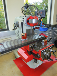
PITCH AND ROLL MEASUREMENT WITH 2D-ZEROTRONIC MEASURING UNIT AND MT-SOFT-SOFTWARE
Subject:
Alignment of a turning lathe with an oblique bed and establishing a pitch and roll measuring protocol for the longitudinal and transversal axis.
Measuring task:
The machine should first be very accurately levelled in both X- and Y-direction.
Afterwards a pitch and roll measuring report with numerical and graphical information is required.
![]()
MEASUREMENT AND CERTIFICATION OF THE TORQUE-RESISTANCE ON AN ENGINE-SHAFT

Subject:
The torque-resistance of an engine shaft is decisive for the reliability and durability of the engine. However, to measure this resistance for long shafts is a challenging task.
Measuring task:
The torsion of an engine-axis mounted on a testing-rig with a base of 12m x 12m must be measured precisely by recording the change of the twist-inclination and by putting it in relation to the applied torque.
![]()