
Page 44 - Lehrbuch Neigungsmessung deutsch 2018.indd
P. 44
COMPENDIUM INCLINATION MEASUREMENT
WYLER AG, WINTERTHUR / SWITZERLAND
6.2.2 HANDHELD MEASURING INSTRUMENTS WITH ANALOG SIGNAL PROCESSING
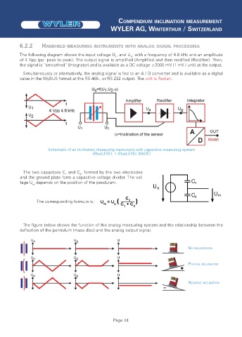
The following diagram shows the input voltage U , and U , with a frequency of 4.8 kHz and an amplitude
2
1
of 4 Vpp (pp: peak to peak). The output signal is amplified (Amplifier) and then rectified (Rectifier). Then,
the signal is “smoothed“ (Integrator) and is available as a DC voltage ±2000 mV (1 mV / unit) at the output.
Simultaneously or alternatively, the analog signal is fed to an A / D converter and is available as a digital
value in the WyBUS format at the RS 485-, or RS 232 output. The unit is Radian.
Schematic of an inclination measuring instrument with capacitive measuring system
(BlueLEVEL + BlueLEVEL BASIC)
The two capacitors C and C , formed by the two electrodes
1
2
and the ground plate form a capacitive voltage divider. The vol-
tage U depends on the position of the pendulum.
m
The corresponding formula is:
The figure below shows the function of the analog measuring system and the relationship between the
deflection of the pendulum (mass disc) and the analog output signal.
NO INCLINATAION
POSITIVE INCLINATION
NEGATIVE INCLINATION
Page 44