BlueMETER SIGMA
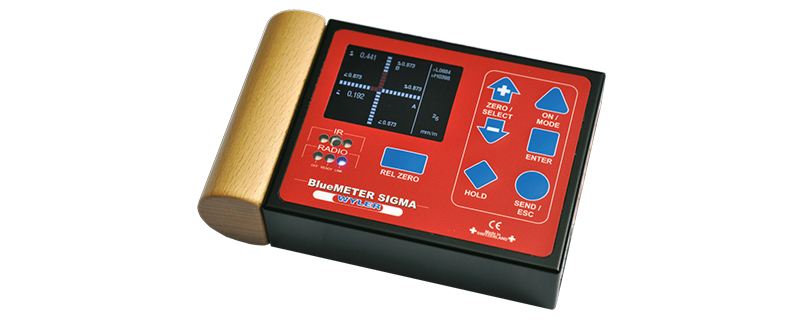
BlueMETER SIGMA is a further enhancement of the well known BlueMETER, and has been developed as an intelligent display unit for the electronic inclination measuring instruments
- BlueLEVEL
- BlueCLINO and BlueCLINO High Precision
- MINILEVEL NT and LEVELTRONIC NT (both by means of cables only)
- CLINOTRONIC PLUS
- ZEROMATIC
- ZEROTRONIC sensors
Besides the excellent measuring accuracy, the measuring instruments BlueLEVEL, BlueCLINO, CLINOTRONIC PLUS and ZEROTRONIC sensors supply a fully digital signal for transmitting these values over long distances without any loss of quality.
BlueMETER SIGMA is a display unit
Functions and features of the BlueMETER Sigma:
- large and very easy-to-read color display
- Various color profiles can be chosen
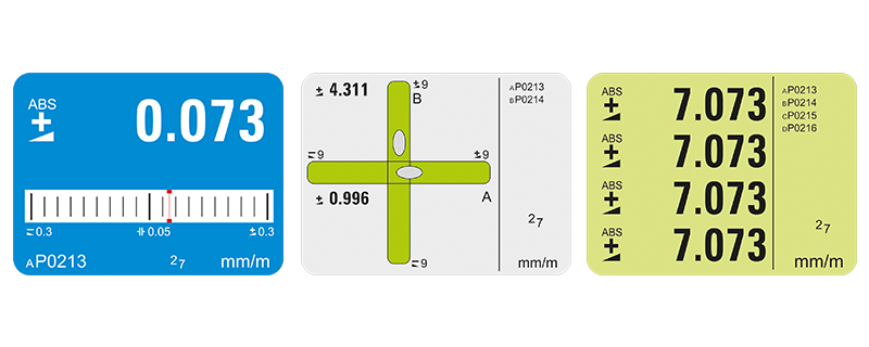
- Various display methods are available
- Measured values of up to four measuring channels can be displayed simultaneously. Users can choose which instrument is displayed as A, B, C or D.
- Furthermore, the following options are available:
- Display of the difference of two instruments (A-B)
- Display of the difference of four instruments (A-B and C-D). The values can then be displayed as a 2D-graph:
A-B for the X-axis, and C-D for the Y-axis.
Graphical 2D-display
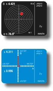
The 2D-display shows graphically the position of an object in space, and the change of its position and makes the information easily understandable.
This substantially facilitates the alignment of e.g.
- a machine
- a truck
- a container hanging on a crane
- a reference plate
- etc.
The following parameters (among others) can be set and changed at the BlueMETER SIGMA:
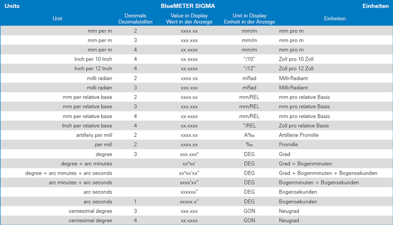
- Units
- Filter settings
- Relative base length
- Physical address of the Zerotronic sensors
Additional functions and features of the BlueMETER SIGMA:
- New design with aluminum housing and latest technology
- Optional radio communication based on Bluetooth® technology: a single worldwide standard
- Display of measuring values in various measuring units (see following list)
- bsolute measurements
- Relative measurements
- Evaluation and storage of the zero-offset of instruments/sensors
- Battery voltage indicator
- Powered by standard 1.5V batteries size C
- CE compatible


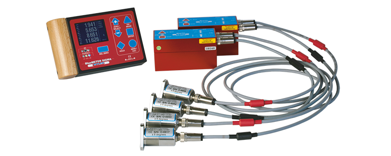
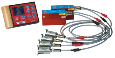
Four ZEROTRONIC sensors connected to a BlueMETER SIGMA by means of two BlueTC

BlueLEVEL, BlueLEVEL-2D und wylerLEVEL Frame connected to a
BlueMETER SIGMA by means of radio transmission

BlueLEVEL, BlueLEVEL-2D und wylerLEVEL Frame connected to a
BlueMETER SIGMA by means of cables

CLINOTRONIC PLUS connected to a BlueMETER SIGMA by means of cables
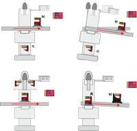
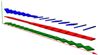
MACHINE TOOLS / CHECKING OF ROTATION ERRORS
Subject:
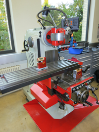
Machine tools must be checked periodically for geometrical deviations, since changes of the geometry have a direct influence on the quality of the parts manufactured on that machine.
It is very important that during the displacement in one axis the tool will follow a straight path compared to the table. On machines of light-weight construction the table can show a deformation due to its own weight.
If the complete machine construction is tilting during the displacement of the table this is a sign for insufficient stability of the foundation or for a flexibility of the stand (damping elements).
Measuring task:
The geometry of a machine tool must be verified. The check must show rotational errors of the table during displacement. The measurement should be made reliably and efficiently.
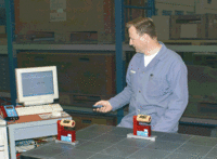
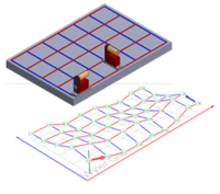
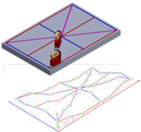
CALIBRATION OF SURFACE PLATES (FLATNESS)
POWER SUPPLY SECTOR / ALIGNMENT OF LARGE PUMP SHAFTS
Subject:
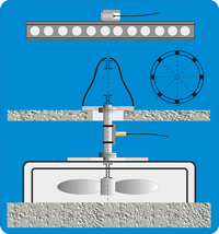
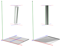
During maintenance works on the pumps of the cooling circuit of a cooling tower in nuclear power plants, quick and precise methods for the required alignment works are indispensable. Large electro motors with vertical axis drive evenly large centrifugal pumps situated one floor below.
Measuring task:
- The horizontal positions of the connecting lines between the bearing faces on the bearing ring for the stator must be checked. The flatness and the horizontal position of the bearing ring must be assured.
- The pump housing, one floor below, must be adjusted horizontally as well.
- The center points of the pump shaft and the drive shaft of the motor must be aligned to each other in order to assure that the transmission shaft can work free of any bending moment.
AIRCRAFT INDUSTRY / ALIGNMENT OF COMPONENTS IN AN AIRCRAFT
Subject:
During assembly, maintenance and repair of a large transport aircraft various components of the equipment must be precisely aligned to a reference platform.
Measuring Task:
Two radar platforms must be aligned precisely parallel to the reference platform. The measurements must be carried out while other teams are working on the same aircraft.
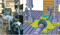
MACHINE TOOLS / SPINDLE ALIGNMENT
Subject:
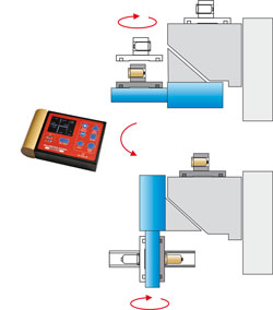
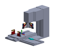
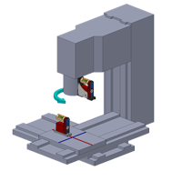
The main spindle of a milling machine can be set for vertical as well as for horizontal milling. To change between the two settings, the milling head rotates on a bearing set at 45°.
Measuring task:
The deviation from the right angle between the two working positions “horizontal” and “vertical” must not exceed 2 arcsec.
The measurement (and correction) is first made during assembly, and again during final inspection of the finished machine.
MEASUREMENT OF THE FLATNESS IN AN OVEN WITH LIMITED HEIGHT
Subject:
A bio-technical company must measure the flatness of plates in an oven (at room temperature), to ensure that all objects stored in that oven are horizontally aligned. Distance between plates are only 100 mm. Size of each plate is 800 mm x 800 mm.
Normally a BlueSYSTEM Sigma together with wylerSPEC is used for flatness measurement. For this application here the height of the instruments exceeds the space available.
Measuring task:
Flatness measurement of the plates in the oven with precision inclination measurement instruments, despite the limited space available.
MEASUREMENT OF THE ABSOLUTE POSITION OF A Guideway
Subject:
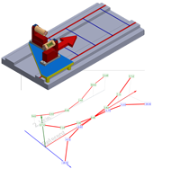
The straightness of a guide way can be measured very easily and very precisely with the software wylerSPEC. Since the straightness is independent of the absolute position of the guide way in space, it is enough to measure “relative”. On the other hand, when adjusting a machine, it can be very helpful to know the exact position of the guide way in space.
Measuring task:
For a guide way, not only its straightness but also its deviation from the horizontal plane shall be measured. Furthermore, it should be shown where and how much the guideway should be corrected to adjust it horizontally.
FLATNESS MEASUREMENT ON A CIRCULAR SUPPORT OF A TURN TABLE
Subject:
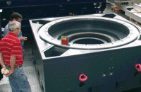
Module 4 of the software wylerSPEC allows users to determine the flatness of a rectangular surface very easily. The measurement of the flatness of a circular support though, as it is used for large machine tools, is much more complex.
Measuring task:
The flatness of a circular support with a diameter of 2.3m must be determined.
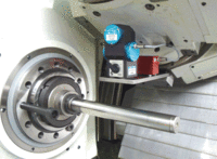
MACHINE TOOLS / ANGULAR POSITIONING ERROR OF A- AND C-AXIS
Subject:
Machine centers capable of machining freely designed shapes, require, next to the linear axes X, Y and Z, the rotary axes A and C as well. In order to manufacture work pieces with adequate precision, the rotary axes A and C must provide the same high angular positioning accuracy as the linear axes.
Measuring task:
To measure deviation from nominal angle at different angular positions. To avoid errors due to the mass of the machine components, the measurement should be collected as close as possible to the cutting position.
The measured values shall be used as corrective factors in the CNC controller. Uncertainty of measurement should not exceed 2 arcsec.
LARGE GRINDING MACHINE WITH FLAT GUIDEWAYS
Subject:
A manufacturer of large metal plates has several large surface grinding machines in his workshop. The geometry of these machines must be checked and documented periodically, and, where required, to be corrected.
Measuring task:
On a surface grinding machine with 18-meter-long guideways, set 1.3m apart, the parallelism of the two guideways must be checked periodically. The guideways must be within a plane with a maximum tolerance (error) of less than 0.1 mm. The complete machine and its guideways can be adjusted by means of supporting screws placed at 750 mm intervals.
MEASUREMENT OF A CIRCLE ON A ROUND TABLE OF A GRINDING MACHINE
Subject:
A manufacturer of large metal plates has several large surface grinding machines in his workshop. The geometry of these machines must be checked and documented periodically, and, where required, to be corrected.
Measuring task:
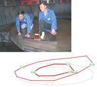
The flatness of a rotating table of a grinding machine with a diameter of 3200 mm must be measured. Thereby only the flatness of a circle must be measured and not the whole table.
MEASUREMENT OF PITCH AND ROLL ON A GRINDING MACHINE
Subject:
A manufacturer of large metal plates has several large surface grinding machines in his workshop. The geometry of these machines must be checked and documented periodically, and, where required, to be corrected.
Measuring task:
On a large surface grinding machine with guide ways with a length of 18m pitch and roll must be checked. The maximum tolerance is 0.1 mm/m.
MEASUREMENT OF THE RECTANGULARITY OF THE HEAD OF A ROUND TABLE GRINDING MACHINE
Subject:
A manufacturer of large metal plates has several large surface grinding machines in his workshop. The geometry of these machines must be checked and documented periodically, and, where required, to be corrected.
Measuring task:
The rectangularity of the axis of a grinding head of large grinding machine in relation to the bearing of a round table with a diameter of 3200 mm must be measured. Based on the results, if necessary, the inclination of the head must be adjusted.
ALIGNMENT OF THE HOLES OF FLANGES
Subject:
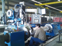
A pipe must be welded in between two vertical flanges with holes. These pipes have a length between 2m and 10m and a diameter between 400mm and 1000mm.
The material of the flanges and the tubes is either aluminum or stainless steel.
Measuring task:
PITCH AND ROLL MEASUREMENT WITH 2D-ZEROTRONIC MEASURING UNIT AND MT-SOFT-SOFTWARE
Subject:
Alignment of a turning lathe with an oblique bed and establishing a pitch and roll measuring protocol for the longitudinal and transversal axis.
Measuring task:
The machine should first be very accurately levelled in both X- and Y-direction.
Afterwards a pitch and roll measuring report with numerical and graphical information is required.
MEASUREMENT AND CERTIFICATION OF THE TORQUE-RESISTANCE ON AN ENGINE-SHAFT
Subject:
The torque-resistance of an engine shaft is decisive for the reliability and durability of the engine. However, to measure this resistance for long shafts is a challenging task.
Measuring task:
The torsion of an engine-axis mounted on a testing-rig with a base of 12m x 12m must be measured precisely by recording the change of the twist-inclination and by putting it in relation to the applied torque.
MONITORING OF AN OFFSHORE WIND TURBINE TRIPOD DURING PLACEMENT AND ANCHORING IN THE SEA
Subject:
An offshore wind turbine requires a stable and exactly horizontal base. To achieve this, the tripod, on which afterwards the wind turbine will be mounted, must be monitored during the anchoring process.
Measuring task:
The position of the Tripod must be monitored during the anchoring rocess with inclination sensors mounted at the upper end of the Tripod. The sensors must withstand the high accelerations occurring during the ramming process. The measured data must be transmitted wireless to the boat controlling the whole process.
RAILWAY CONSTRUCTION
Subject:
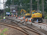
The requirements in railway construction are increasing continuously. Specifically, high speed tracks put very high demand on track geometry and therewith on track construction. A tamping machine requires exact information about the condition and position of the track ahead to make the required corrections and to work precisely and efficiently
Measuring task:
The positioning errors of the track shall be measured with a mobile measuring unit. The measuring data shall then be used by the tamping machine.
ALIGNMENT OF SOLAR PANELS
CALIBRATION OF ROBOTS
Subject:
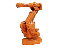
The precision of an industry robot is directly depending on the precise alignment of each single axis.
Measuring task / Goal:
The offset of each axis has to be measured not only in
production, after mounting the robot, but also after the
installation at customer site. These offsets are then to be known and compensated by the process control system.
